
Many people think that BPMN notation hides secrets and mysteries. In fact, it’s the most widely used and accepted notation in the world, precisely for its ease of use and the intuitive process flow diagram symbols that it employs.
In this post you will find out the 5 categories of flow diagram symbols in BPMN, and how to use them in your process diagrams.
Know more: Why and how to use the most accepted BPMN 2.0 notation
The 5 categories of BPMN process flow diagram symbols
1- Flow elements
They define when a process starts, when it finishes, what tasks occur and what deviations happen inside the flow and tasks. They’re the ones that indicate the content of the process.
Start:
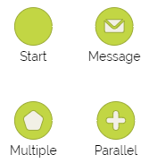
Represented by a green circle, there are several types, among them:
- The timer starts a process based on a date or cycle.
- The conditional starts a process when a formula is true.
- The multiple start event indicates that the process can start in a number of different ways, for example by a call from a client or by an internal request from another area.
- In the parallel start event, it’s necessary that more than one condition occur, for example, it’s necessary that another internal area approves both a telephone client and the beginning of the process.
- There’s also a specific symbol for a message that starts the process, among many others.
End:

Indicated by a red circle, it can also have several types, see some of them:
- The final multiple event indicates that the end of the process will trigger several consequences, and the end shows that when this event occurs, you must terminate all other process tasks.
- The message throw a message to other pool.
- The terminate finishes all tokens in a process instance.
Events:
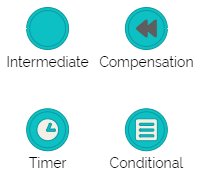
Symbolized by a blue circle, they also have various types, some of them represented below:
- The conditional event can only occur in function of a certain condition being true; and you use compensation when you need to compensate for an earlier activity in the process.
- The timer can represent a delay or a trigger (boundary).
Tasks:

They are represented by rectangular boxes with rounded edges and show the actions that must be performed, they can also have several modalities, such as:
- Business rule tasks follow a certain pre-established rule and the manuals are executed without the aid of software or systems.
- Service tasks allows the integration with information systems.
- Send Task can synchronize pools.
Gateways:

Indicated by yellow diamonds, these are the most diverse elements.
Exclusive gateways are those in which only one of the output branches will continue with the task flow.
With the parallel, two or more branches of the task sequence open and occur simultaneously.
In Inclusive gateways, there is a condition configuration on each flow, and one or many of them can be triggered.
To see even more types of deviations as they’re used BPMN process flow diagram symbols, check out this blog post: Gateways: exclusive, inclusive and many others!
2- Lanes and pools
These are the places where you place flow elements and sets of activities, dividing them into lanes which represent the departments or participants responsible for certain tasks.
A pool represents a business process. You can add multiple pools in a diagram and connect them with send-receive elements (Send Task, Receive Task, Send Intermediate etc).

Understand in more detail how pools and lanes work: BPMN Swim Lane and Pool Lane BPMN: Dive into these tips!
3- Connectors
You need to connect flow elements in order to know the sequence of tasks and the type of relationship between each process element.
See their variations:
Message passing: 
Simple connection: 
Association:
Attaches data objects to a task. ![]()
4- Data elements
These indicate how data is manipulated, stored and queried by agents in the flow, see some examples:

5- Notes
You need to document some tasks with notes, which make the flow of the diagram clearer to the reader.
Check out this symbol note:

If you want to even better understand BPMN process flow diagram symbols, check out this lesson on BPMN modeling:
